Usually, it is impossible to avoid using 3D printing support structures for overhangings and bridges as it might affect the quality of your print. When selecting the suitable support settings, your print have achieved half of success. But do you know what's the best support settings for resin 3D printing? The name of support settings maybe differ according to various slicers. In order to have a better understanding of those settings, let's take Chitubox as an example.
Download ChiTuBox: https://www.chitubox.com/download.html
Download ChiTuBox: https://www.chitubox.com/download.html
The support settings of ChiTubox, as illustrated below.


1. Raft
Raft is the first layer which is also called attachment layer as the primary purpose of a raft is to help with bed adhesion. The raft is printed directly on the platform, then the object and support are printed above the raft. The exposure time for the rafe is at least 10 times the regular exposure time to make sure that any potential gap between the build platform and vat floor is fully cured and the first layer is attached to the platform firmly.
In ChiTuBox, there are 5 settings related to raft. Let's discuss them one by one.

1.1 Raft Shape
ChiTuBox provides a skate raft shape, as illustrated below. When there is no raft shape, the layers adhered on the build plate are pieces of bottoms. The skate raft is covered on the bulid plate with a whole piece which expands the contact area to improve the adhesion. The cocked edge of the skate raft comes into play when removing the model from the build plate.

Left: None Right: Skate
1.2 Raft Area Ratio(%)
Raft area ratio has great effect on the proportion of the raft. The greater the proportion is, the the stronger the adhesion will be. But certainly it also increases consumption of material and removal of supports might sometimes be tricky.

Left: Raft Area Ratio(110%) Right: Raft Area Ratio(180%)
1.3 Raft Thickness(mm)
As the name implies, it is the thickness of the raft. Usually, the thicker the raft is, the stronger the adhesion will be. But the consumption and the separation are still headaches for desigers.

Left: Raft Thickness(1mm) Right: Raft Thickness(5mm)
1.4 Raft Height(mm)
Just like raft thickness, it is the height of the raft. The higher the raft is, the easier it will be to find the key point to seperate the print from the build plate. Also, it means more material consumption.
Left: Raft Height(1.8mm) Right: Raft Height(5mm)
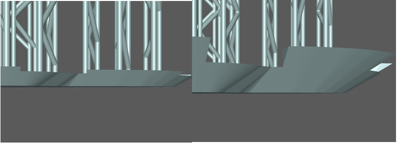
1.5 Raft Slope(°)
Raft Slope is the angle between the raft edge and the horizontal plane. Usually, the smaller the angle is, the easier it will be to scoop up the model from the building plate according to the lever principle.

Left: Raft Slope(20°) Right: Raft Slope (80°)
2. Z lift height
Z lift height is the distance between 3D model and bulid plate. To adjust Z lift height for 3D model, it will not be printed directly on the platform but on supports and raft. The lifting height should be set to 7 mm for large build platform and 5 mm Z lift height for small build platform, with a lifting speed of 10 mm/min.


Left: Z lift height(20mm) Right: Z lift height(5mm)
3. Top
Top refers to the top part of the support. The top part is the key factor to link the model and support. If the support top is not thick enough, the 3D model maybe separate from the support due to the cured separation forces from FEP/PDMS on the printed object.

3.1 Contact Shape
The sphere contact shape is like a ball to increase the contact area between the print and the support. In addition, when removing the support, diagonal cutting pliers can be used to cut off the sphere from where the support is connected, making it less likely to damage the model. Some rigid resins are relatively brittle. Cutting may easily leave remarkable holes on the surface of the model.

3.2 Contact Diameter(mm)
The contact diameter directly reflects in the contact area between the model and the support. The longer the contact diameter, the stronger it stick to the object and the harder the dismantling with small diagonal cutting pliers.

3.3 Contact Depth(mm)
The deeper the contact depth, the deeper the support tip inserts into the model.

3.4 Connection Shape
There are three connection shapes in ChiTuBox: cone, pyramid, skate as illustrated below from left to right. Oviously, the sections from cone to pyramid are on the decrease. They don’t have much special differences so you can choose one depending on your needs.

3.5 Upper Diameter(mm)
Upper diameter refers to the diameter of support tip. Usually, the thicker the upper diameter, the stronger the support is. But sometimes, thicker is not better as it may look a bit top-heavy.

3.6 Lower Diameter(mm)
Likewise lower diameter is the diameter of the bottom of the top part. It's helpful to reasonably adjust the lower diameter to avoid that the middle part cann’t afford the heavy top.

3.7 Connection Length (mm)
This feature allows designers to customize the connection length. An appropriate connection length can ensure that the support top is rough enough and easier to remove.

4. Middle
The middle part of the support have the ability to act as the spine for the human. The strength of the middle determines the strength of the support.

4.1 Shape
Like connection shape, there are also three slections for middle shape in ChiTuBox: prism, cube, cylinder as illustrated below from left to right. The system default is cylinder.

4.2 Diameter(mm)
As the mainstay of the support, when the diameter of the middle increases, the support is rougher. Meanwhile, more materials will be used. Also you need to pay attention to the middle and the top in perfect proportion and harmony.

4.3 Angle(°)
Angle is the angle between the support top and the vertical. When the support top has an angle of 90 degrees with the contact surface of the print(normal vector), the force to the surface will also be vertical and the contact depth between the support and the surface is thinner so that it is easier to remove the support.

Left: Angle(10°) Middle: Angle(30°) Right: Angle(60°)
5. Bottom
Bottom is the support pedestals. Sometimes there are no rafts. So the bottom will be the attachment layer to help with bed adhesion. And when we have to generate support structures on the model itself, the bottom will come into play.

5.1 Platform Touch Shape
ChiTuBox offers 5 types of bottom as illustrated below from left to right: skate, cone, cube, cylinder and prism. You can do it however you like but the skate and cone one may be much easier to seperate from build plate due to their cocked edges.

5.2 Touch Diameter(mm)
It works the same way as the raft area ratio (see 1.2) to enhance the adhesion on the build plate. And the consumption of material and removal of supports are still need to be considered.

Left: Touch Diameter(12mm) Right: Touch Diameter(20mm)
5.3 Thickness
What you can see is that the thicker the bottom thickness, the smaller the contact area is. So, the thickness is not the more, the better.

Left: Thickness (1mm) Right: Thickness (2mm)
5.4 Model Contact Shape
Depending on the complexity of the 3D model with overhangings and bridges, sometimes we have to generate support structures on the model itself. Similar to the top, the tottom takes the small balls to increase the contact area and protect the the surface of the model when removing the support.

Left: None Right: Shpere
5.5 Contact Diameter(mm)
The contact diameter directly reflects in the contact area between the model and the support bottom. The longer the contact diameter, the stronger it stick to the object and the harder the removal.
Left: Contact Diameter(0.6mm) Right: Contact Diameter(0.8mm)
5.6 Contact Depth(mm)
The deeper the contact depth, the deeper the support bottom inserts into the model.

Left: Contact Depth(0.2mm) Right: Contact Depth(0.6mm)
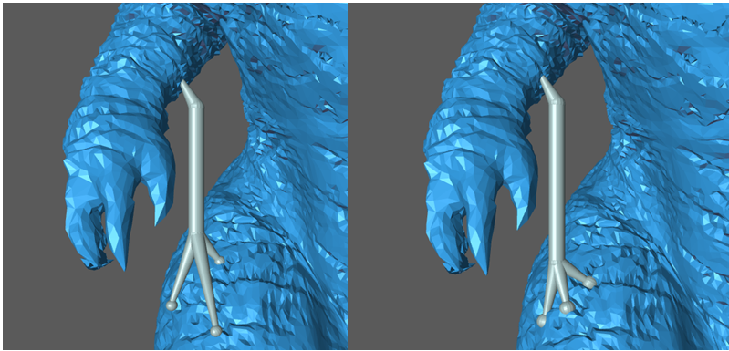
5.7 Contact Point
The more the contact point, the stronger the ability is to grip the surface. Also the tripod construction leads to more stable whole structure.

Adding 3D printing support is an academic issue rather than a technology. 3D printing complex models, many find it difficult to decide when and where to use support structures. Fortunately, ChiTuBox not only provides various powerful support settings, but aslo automatically places support structures where they are needed based on the parameters you set which makes things simple.
More Reading:
Improve Surface Quality in 3D Printing by Optimizing Part Orientation
Troubleshooting! Prints aren’t sticking to the build plate!
The Factors to Affect the Print Speed of A Resin(SLA/DLP/LCD) 3D Printer
More Reading:
Improve Surface Quality in 3D Printing by Optimizing Part Orientation
Troubleshooting! Prints aren’t sticking to the build plate!
The Factors to Affect the Print Speed of A Resin(SLA/DLP/LCD) 3D Printer
Comments
Post a Comment